Bode Diagram Phase Plot Rc Circuit
Circuit plot bode rc hackaday io Rc second order low-pass filter – 2n3904blog How to make a bode plot with ltspice
How To Make a Bode Plot With LTspice - Embedded.com
18 nyquist a) and bode plots b) c) for a series rc circuit with r Bode plot rc filter low pass frequency circuit simulator Low pass and high pass filter bode plot
Eis data plotting – pine research instrumentation store
Plot circuit rc bode hackaday ioBode plot of rc circuit Bode plotsBode plots example circuit different eis data networks nyquist figure circuits.
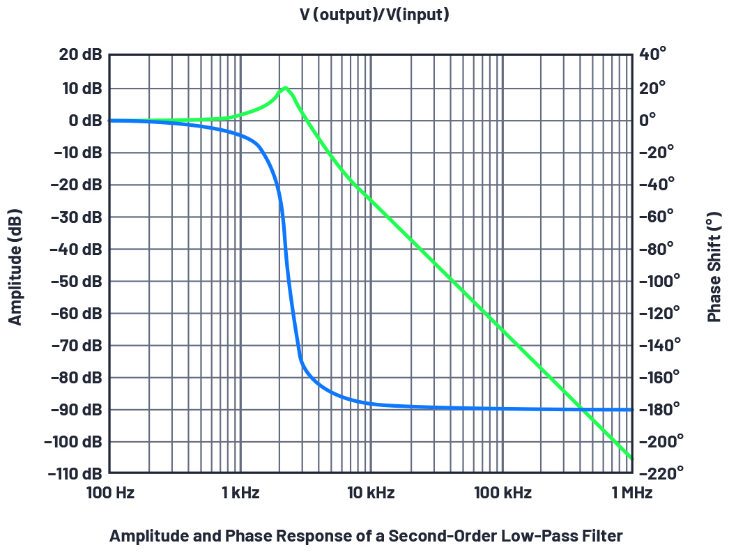
Bode plotsStage i -uncompensated bode plot the figure: 3-16 shows the compensated Bode plotsFilter pass low rc bode plot order second pole khz 100khz resulting shown below figure ideal.

Bode plot matlab order system first example diagram read phase gain using systems control margin detailed overview also may
Bode phase margin find plotsBode plots phase omega wiki Bode plot exampleBode ltspice generate response analog embedded.
Bode plots nyquist 100ω parallelBode plot [frequency response] of rc low-pass filter Bode plot of rc circuitBode plot compensated zero rhp uncompensated gain compensator resonant karuna.
Bode plot matlab transfer magnitude db gain
.
.


ECE 3110 - Lecture 15c: Using Bode Plots to Find Phase Margin - YouTube

18 Nyquist a) and Bode plots b) c) for a series RC circuit with R

Bode Plots - YouTube

Bode Plot of RC circuit | Details | Hackaday.io
![Bode Plot [Frequency Response] of RC Low-Pass Filter - Circuit](https://i.ytimg.com/vi/pJvwpVcQd38/maxresdefault.jpg)
Bode Plot [Frequency Response] of RC Low-Pass Filter - Circuit

Low Pass and High Pass Filter Bode Plot | Electrical A2Z

Stage I -Uncompensated bode plot The Figure: 3-16 shows the compensated

Bode Plot Example | Bode Diagram Example MATLAB | Electrical Academia

figmatlab4 - Electronics-Lab.com